
3D Graphics
Blender Shader Editor Explained: Understanding Nodes, Materials, and PBR Workflows
When you first start working with materials in Blender, the Shader Editor is where you’ll spend most of your time. At first glance, you’ll see a node graph with connections, but it’s crucial to understand that this isn’t just a color-editing panel. The Shader Editor is where you define how a surface interacts with light.
There’s a common misconception among newcomers. Many treat the Shader Editor as simply “a place to load texture files,” but it’s actually a full material authoring workspace where you connect textures, utility nodes, and shaders to build the physical properties of your surface. You’re not just assigning color—you’re designing reflectivity, roughness, metallic properties, transparency, and normal direction all within a single node graph.
Blender uses a node-based material workflow. Each node performs a specific function, and you build your final material by connecting these blocks together. It’s similar to layer compositing in Photoshop, but the connection structure and data flow are much more explicit and visible. Rather than memorizing every node name, understanding how data flows through your graph to become a material is what matters first.
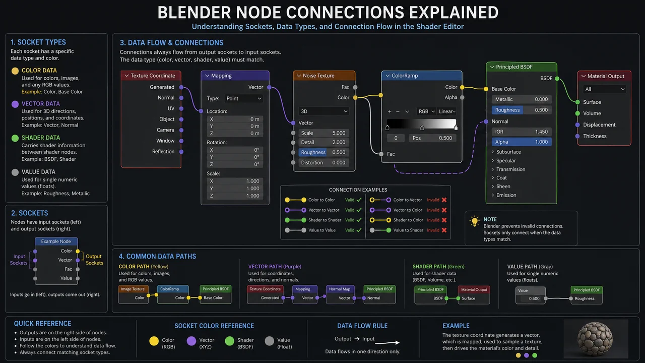
Understanding the Basic Node Workflow
The first thing to grasp in the Shader Editor is how data moves through your network. Nodes don’t exist in isolation—they pass data in a directional flow: top to bottom, left to right. Once you understand this flow, you can quickly troubleshoot when something isn’t working.
The foundation of every material setup uses three core nodes. Image Texture loads your external image file, Principled BSDF defines the physical properties of your material, and Material Output sends the final result to the renderer. These three nodes form the backbone of every Blender material.
Image Texture brings external image files into Blender. The color data output from this node connects to inputs on Principled BSDF—things like Base Color, Roughness, and Metallic. Principled BSDF processes this data, calculates the physical behavior of your surface, and passes the result to Material Output, where it gets rendered.
Any node that isn’t connected to Material Output has zero impact on your render. You could build an incredibly complex node graph in the Shader Editor, but if it doesn’t ultimately connect to the Surface input on Material Output, it renders as an empty material. A lot of beginner frustration over “invisible materials” comes down to this missing connection.
As your node graphs become more complex, always verify your connection to Material Output first. Every time you add or modify nodes, check that your data flow remains unbroken. It’s the fastest way to catch issues before they waste your time.
Navigating the Shader Editor Interface
The Shader Editor breaks down into four main regions. Understanding what each one does helps you find the tools you need without wasting time hunting through menus.
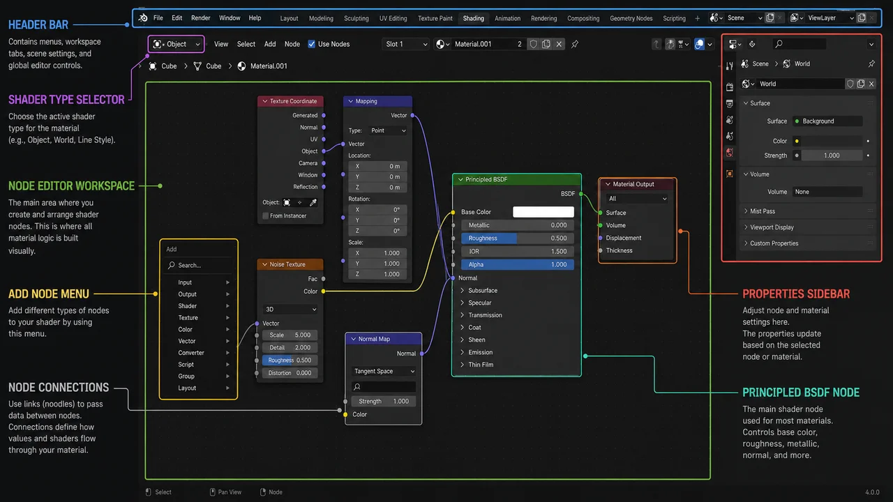
| Region | Role | Beginner Priority |
|---|---|---|
| Header | Add Menu, Mode Toggle, Search | High |
| Node Area | Node Layout and Connections | Essential |
| Sidebar | Node Selection Options, Group Management | Medium |
| Properties | Material Creation, Slot Management | High |
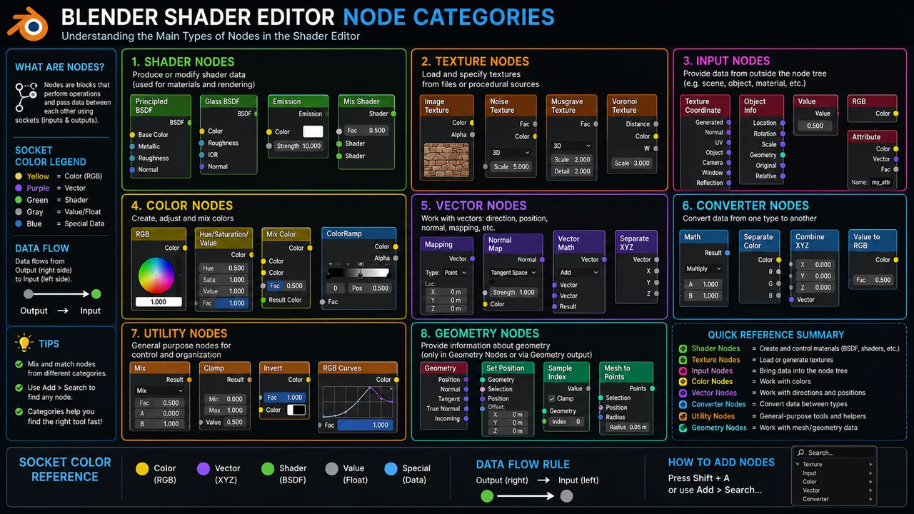
The Header contains the Add Menu—your primary tool for introducing new nodes into the shader network. You’ll find it organized into intuitive categories like Shader, Texture, Input, Vector, and Converter. Hit Shift+A to invoke it quickly, and lean on the search function when you’re unsure of a node’s name. It’s a real time-saver.
The Node Area is where the real work happens in the Shader Editor. This is your canvas for laying out and connecting nodes, and it’s where your entire material structure becomes visually apparent. When something breaks in your material, this is the first place to look. You can immediately spot disconnected links or nodes wired into the wrong sockets right here.
The Properties panel sits on the right side of the Shader Editor and manages all material data for your current object. Use it when you need to create a new material, swap out an existing one, or juggle multiple material slots. Often, you’ll set up your material here before even opening the Shader Editor.
Essential Nodes Every Beginner Should Know
While the Shader Editor contains dozens of nodes, beginners typically work with only a handful on a regular basis. Master these five core nodes and understand how to wire them together, and you’ll have everything you need to build most basic materials.
Principled BSDF
Principled BSDF is the workhorse of Blender’s material workflow. Whether you’re creating metal, plastic, wood, or glass, this single node can handle virtually all of them. Think of it as Blender’s equivalent to Maya’s aiStandardSurface, and you won’t be far off.
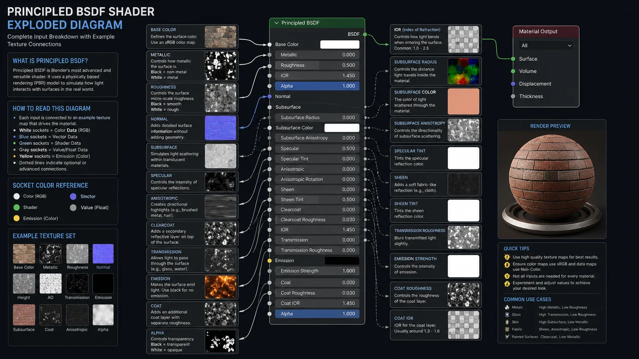
The key inputs you’ll use most are Base Color, where you plug in your albedo or diffuse texture. Roughness controls surface micro-detail—lower values mean shinier surfaces. Metallic toggles between 0 and 1 to define how metal-like your material is. And Normal accepts your normal map data to add surface detail without extra geometry.
Image Texture
Image Texture is your gateway node for bringing external texture files into the shader network. It’s where PBR workflows start. You’ll typically load separate textures for Base Color, Roughness, Metallic, and Normal, each in its own Image Texture node, then connect them to their corresponding inputs.
The critical setting here is Color Space. For color data like Base Color, set it to sRGB. For data-only textures like Roughness, Metallic, and Normal, switch to Non-Color. Miss this step and your material colors and surface properties will render incorrectly.
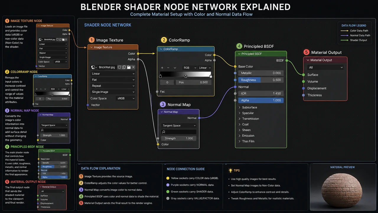
Mapping and Texture Coordinate
Mapping lets you adjust texture position, rotation, and scale without touching your UVs—perfect for quick adjustments. Texture Coordinate determines how your texture projects onto the model surface. Typically you’ll connect the UV output from Texture Coordinate into Mapping’s Vector input.
Normal Map
Normal Map is the conversion node that translates normal texture data into surface direction vectors. Plugging an Image Texture directly into Principled BSDF’s Normal input without this step causes surface distortion. Always run normal data through the Normal Map node first.
| Node | Purpose | Frequency of Use |
|---|---|---|
| Principled BSDF | Defines material physical properties | Essential |
| Image Texture | Loads external image files | Very High |
| Material Output | Final output to renderer | Essential |
| Normal Map | Converts normal map data | High |
| Mapping | Adjusts texture placement and scale | High |
| Texture Coordinate | Controls UV projection method | High |
Building Your First Material
Once you understand the concepts, the fastest way to learn is by building an actual material. We’ll use wood as our example. Wood requires Base Color, Roughness, and Normal maps, making it ideal for learning the full PBR texture workflow.
Select your object and create a new material in the Properties panel. The Shader Editor will automatically place a Principled BSDF and Material Output node. Press Shift+A and add three Image Texture nodes, then load your Base Color, Roughness, and Normal texture files into each.
Roughness Texture (Non-Color) → Principled BSDF Roughness
Normal Texture (Non-Color) → Normal Map → Principled BSDF Normal
Connect the Color output from your Base Color texture to Principled BSDF’s Base Color input. For Roughness, connect the Color output directly to the Roughness input. For Normal, pipe it through a Normal Map node first, then into the Normal input. These three connections alone create a functional wood material.
Mapping and Texture Coordinate nodes aren’t required, but add them when you need to scale or position textures. Connect Texture Coordinate’s UV output to Mapping’s Vector input, then feed Mapping’s Vector output into each Image Texture’s Vector input. This lets you adjust all your textures from a single control point.
Common Material Types in Blender
Most material workflows in Blender can be built by combining inputs on the Principled BSDF shader. Below are the core parameter settings for each material type. You can quickly establish base materials using values alone, without textures.
| Material Type | Key Settings | Important Notes |
|---|---|---|
| Plastic | Roughness 0.3~0.5, Metallic 0 | Gloss variation is significant based on Roughness value |
| Metal | Metallic 1, low Roughness | Base Color determines metallic hue |
| Wood | Connect PBR textures | Normal Map required |
| Glass | Transmission 1, Roughness 0 | Enable transparency in render settings |
One common mistake when building metallic materials is setting a high Metallic value but getting results that look off. Usually, the culprit is a Base Color that’s too bright or too dark. Real metal albedo values are actually quite dark, and dialing down your Base Color will give you a more convincing metallic look.
Glass materials rely on setting Transmission to 1 as a baseline, but your renderer settings must have transparency enabled to render correctly. Be aware that EEVEE and Cycles handle glass materials differently, so switching renderers can change your results—it’s worth checking this ahead of time.
Performance Tips
As your node graph becomes more complex in the Shader Editor, render times and viewport performance will take a hit. Deeply nested Procedural nodes or unnecessary large textures stacked together can cause noticeable slowdowns.
- Avoid excessive Procedural nodes: complex procedural textures are computationally expensive. If the final result is the same, consider baking the texture ahead of time instead of keeping it procedural.
- Optimize texture resolution: oversized textures relative to screen space waste memory and render time. 4096×4096 isn’t always the answer.
- Reuse Node Groups: when identical node structures repeat, wrap them into a Node Group for easier management and batch updates across your materials.
Materials with multiple stacked Procedural nodes can create bottlenecks in both viewport updates and final renders. Complex procedural setups are useful during development, but you should evaluate baking them to textures before the final render pass.
Common Shader Editor Mistakes
Four recurring mistakes show up when artists first start working in the Shader Editor. Most of these manifest as materials looking strange or not displaying at all.
Wrong Color Space
The Image Texture node’s Color Space setting is misconfigured. Loading Roughness, Metallic, or Normal textures as sRGB causes the values to be misinterpreted as color data, breaking the material. These textures must always be set to Non-Color.
| Texture | Color Space |
|---|---|
| Base Color | sRGB |
| Emission | sRGB |
| Roughness | Non-Color |
| Metallic | Non-Color |
| Normal | Non-Color |
| Height | Non-Color |
Missing UV Map
If your object has no UV map or the UVs aren’t unwrapped when you connect an Image Texture, the texture won’t display correctly. Especially if you’ve modified your base mesh and haven’t re-unwrapped, textures stretch or place incorrectly. When an Image Texture looks wrong, check your UV Editor first.
Normal Map Connected Directly
Connecting a Normal texture straight from Image Texture into Principled BSDF’s Normal input, skipping the Normal Map node. Without that conversion step, the data doesn’t transform properly and your surface gets distorted or overly warped. Always insert a Normal Map node between your texture and the Principled BSDF.
Forgotten Material Assignment
You’ve created a material but it’s not showing up on your object. Even if the material exists in the Properties panel, it won’t render if it’s not actually assigned to the object. When working with multiple objects, make it a habit to check that material slots aren’t empty.
FAQ
What should I do if the Shader Editor won’t open or nodes aren’t visible?
First, make sure an object is selected. The Shader Editor displays materials for the currently selected object, so if nothing’s selected, you’ll see nothing or an empty view. After selecting your object, also verify that a material is actually assigned in the Properties panel. If there’s no material at all, the Shader Editor stays blank.
Does the Shader Editor work differently between Cycles and EEVEE?
The node structure itself is the same, but some nodes and material features can produce different results depending on which renderer you’re using. Physically-based effects like glass transparency, refraction, and Subsurface Scattering may require separate settings in EEVEE or render more limitedly. Since switching renderers after finishing your material can change the look, it’s safer to decide on your final renderer first, then build your materials.
Is it better to build materials purely with Procedural nodes or use texture files?
Rather than picking one as universally better, choose based on your needs. Procedural methods offer unlimited tiling resolution and easy tweaking. However, complex procedural stacks can increase render times, and photorealistic textures often work better with actual texture files. Fast prototyping typically goes Procedural; when final quality matters, PBR texture files are the standard choice.
- The Shader Editor is where you connect textures and shaders to define a surface’s physical properties.
- The basic flow is Image Texture → Principled BSDF → Material Output.
- Nodes that aren’t connected to Material Output don’t appear in renders.
- Color Space: set Base Color to sRGB; all data textures (Roughness, Metallic, Normal) to Non-Color.
- Normal textures must always pass through a Normal Map node before connecting to Principled BSDF.
- Materials can look different between EEVEE and Cycles, so lock in your renderer choice early.
- When first learning the Shader Editor, practice with examples like wood that use all three texture types (Base Color, Roughness, Normal) together.
- When troubleshooting materials, check in this order: Color Space → UV Map → Node Connections.
- If you find yourself repeating the same node structure, wrap it into a Node Group.
- As Procedural nodes multiply, evaluate whether to bake before the final render.
- Blender versions vary in UI layout and node naming, so check the official docs before starting work.
※ This article is based on public resources and real production workflows. Version, licensing, and commercial use terms may change, so please refer to official documentation as well.